LED Matrix Sound Visualizer
What is a Sound Visualizer?
In this tutorial, we want to use a microphone to record the ambient sound, then filter different frequencies out of the sound. This is done by a so called "fast Fourier transform" and is usually a complex operation, but can quickly be made by an FPGA. Finally, we want to display the result with an LED matrix.
What you need
Important: These links below are only for German products.
1. Electronics
*These links are Affiliate Links, by purchasing with them, you support us and our work. As a customer, you pay the same price, we receive part of their revenue through commission.
If you want to work on FPGA projects in a team, you can check out ONE WARE Studio!
The hardware
Soldering
As there are no cheap level shifter boards pre-soldered, I highly recommend learning some soldering skills. You could go ahead and plug the headers in the holes, but this doesn't ensure a connection and that the headers stay in place. Also soldering is has multiple benefits and can be used for many possible projects. Here is a cheap soldering station.
Alternatively, here is a more expensive level shifter that comes pre-soldered.
Here is an example of how to solder the headers to the level shifter.
Electronics
The led matrix* has to be connected with through a level shifter with the FPGA board, as the matrix works with 5V. The level shifter converts the 3.3V outputs of the FPGA to 5V outputs. Here you can see how to connect the matrix:
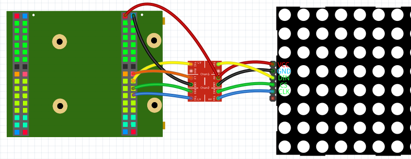
5V and GND have to be connected with HV and GND of the level shifter and VCC and GND of the matrix. 3.3V has to be connected with LV of the level shifter. The 3 I/Os of the FPGA have to be connected with the LV I/Os of the level shifter. The LV I/Os then with the matrix.
To connect the microphone, all you need to do is connect 3.3V and GND of the microphone with 3.3V and GND of the FPGA and connect the rest of the pins (except for SEL) with the FPGA I/Os.
The software
Start by creating a new project, and import the MAX7219_Interface library folder, the Spectrum_Analyzer library folder, the I2S_IN and the SPI library. Important: make sure that you assign Brightness and Shutdown values or remove them from NewComponent. Also Config has to change from '0' to '1' when the matrix is connected. Now you can copy this example:
Main
(
    --MEMS Microphone
    LRCLK         : OUT STD_LOGIC;
    BCLK          : OUT STD_LOGIC;
    Data          : IN STD_LOGIC;
    --LED Matrix
    CS_O          : BUFFER STD_LOGIC;
    CLK_O         : OUT STD_LOGIC;
    DIN_O         : OUT STD_LOGIC;
)
{
    CONSTANT volume_divider : NATURAL := 8;     -- lower value = higehr volume
    CONSTANT offset         : INTEGER := 6130;  -- Microphone value += offset, so median is 0

    --Reads the Microphone library
    SIGNAL I2S_Interface_IN_Data_L             : STD_LOGIC_VECTOR (18-1 downto 0);
    SIGNAL I2S_Interface_IN_Data_R             : STD_LOGIC_VECTOR (18-1 downto 0);
    SIGNAL I2S_Interface_IN_Ready              : STD_LOGIC;
    NewComponent I2S_Interface_IN
    (
        CLK_Frequency      => 12000000,
        Sampling_Frequency => 32000,
        Data_Width         => 18,
        Sample_Bits        => 32,
        BCLK_Edge          => '1',

        Reset              => '0',
        LRCLK              => LRCLK,
        BCLK               => BCLK,
        Data               => Data,
        Data_L             => I2S_Interface_IN_Data_L,
        Data_R             => I2S_Interface_IN_Data_R,
        Ready              => I2S_Interface_IN_Ready,
    );

    --Analyzes the micophone data
    SIGNAL Spectrum_Analyzer_data_o    : Spectrum_Type;
    SIGNAL Spectrum_Analyzer_New_Data  : STD_LOGIC;
    NewComponent Spectrum_Analyzer
    (
        CLK_Frequency     => 12000000,
        Sample_Frequency  => 10000,
        Frequency_Numbers => 16,
        Range_Multiplier  => 2,

        adc_in            => resize((SIGNED(I2S_Interface_IN_Data_L)+offset)/volume_divider, 8),
        New_Data          => Spectrum_Analyzer_New_Data,
        data_o            => Spectrum_Analyzer_data_o,
    );

    --Create the LED Matix bitmap and initialize the matrix
    Process ()
    {
        Thread
        {
            --Load settings (brightness and shutdown)
            LED_Matrix_Config <= '0'; --Wait on start (not absolutely necessary)
            Wait(10ms);
            LED_Matrix_Config <= '1'; --Send settings
            Step{ LED_Matrix_Config <= '0'; }
            Wait(10ms);

            While(true)
            {
                ParFor(i IN 0 to 31)
                {
                    If(Spectrum_Analyzer_data_o(i) > 127){LED_Matrix_Panel_Bitmap(i)(0) <= '1';}Else{LED_Matrix_Panel_Bitmap(i)(0) <= '0';}
                    If(Spectrum_Analyzer_data_o(i) > 64) {LED_Matrix_Panel_Bitmap(i)(1) <= '1';}Else{LED_Matrix_Panel_Bitmap(i)(1) <= '0';}
                    If(Spectrum_Analyzer_data_o(i) > 31) {LED_Matrix_Panel_Bitmap(i)(2) <= '1';}Else{LED_Matrix_Panel_Bitmap(i)(2) <= '0';}
                    If(Spectrum_Analyzer_data_o(i) > 15) {LED_Matrix_Panel_Bitmap(i)(3) <= '1';}Else{LED_Matrix_Panel_Bitmap(i)(3) <= '0';}
                    If(Spectrum_Analyzer_data_o(i) > 7)  {LED_Matrix_Panel_Bitmap(i)(4) <= '1';}Else{LED_Matrix_Panel_Bitmap(i)(4) <= '0';}
                    If(Spectrum_Analyzer_data_o(i) > 3)  {LED_Matrix_Panel_Bitmap(i)(5) <= '1';}Else{LED_Matrix_Panel_Bitmap(i)(5) <= '0';}
                    If(Spectrum_Analyzer_data_o(i) > 1)  {LED_Matrix_Panel_Bitmap(i)(6) <= '1';}Else{LED_Matrix_Panel_Bitmap(i)(6) <= '0';}
                    If(Spectrum_Analyzer_data_o(i) > 0)  {LED_Matrix_Panel_Bitmap(i)(7) <= '1';}Else{LED_Matrix_Panel_Bitmap(i)(7) <= '0';}
                }

                --Update image -> show already defined image
                LED_Matrix_Update     <= '0';
                Step { LED_Matrix_Update <= '1'; }

                --Wait for new data
                While(Spectrum_Analyzer_New_Data = '0') {}
            }
        }
    }

    --Output the matrix data
    SIGNAL LED_Matrix_Panel_Bitmap  : LED_Matrix_Array ((4*8)-1 downto 0);
    SIGNAL LED_Matrix_Update        : STD_LOGIC;
    SIGNAL LED_Matrix_Config        : STD_LOGIC;
    NewComponent MAX7219_Interface
    (
        CLK_Frequency => 12000000,
        Panels        => 4,
        Rotate_seg    => '1',
        Mirror        => '1',

        Reset         => '0',
        CS_O          => CS_O,
        CLK_O         => CLK_O,
        DIN_O         => DIN_O,
        Panel_Bitmap  => LED_Matrix_Panel_Bitmap,
        Update        => LED_Matrix_Update,
        Config        => LED_Matrix_Config,
    );
}
This example displays the analyzed frequencies with an 8x32 LED matrix.
Make sure that you choose the correct FPGA Pins that are connected with DIN, CL and CLK, that 3.3V is connected with the level shifter and that 5V is connected with the level shifter and the matrix.
You can find the full example here.
Conclusion
This is one example of a cool useful project with an LED matrix. Here are some more:
Possible problems
Matrix is dark
- Check is everything connected properly. (Is 3.3V, 5V and GND connected? Does the level shifter have a connection? Are the correct pins used?)
- Is the program correct? (Shutdown => '0'? Does LED_Matrix_Config change from '0' to '1' when the matrix has power?)
- Does the matrix have a MAX7219 IC?
- Check if the I2S_Interface_IN_Data_L data changes, so the microphone works properly. This code outputs the value with the matrix:
While(true)
{
    For(i IN 0 to 17)
    {
        LED_Matrix_Panel_Bitmap(i)(0) <= I2S_Interface_IN_Data_L(i);
    }

    --Update image -> show already defined image
    LED_Matrix_Update     <= '0';
    Step { LED_Matrix_Update <= '1'; }

    Wait(50ms);
}
Last column always on
Try to play around with the offset constant. The last column is the one for the lowest frequency and an offset is interpreted as a very low frequency.
Not sensitive enough
You can set a lower value as volume_divider to increase sensitivity.
We hope you enjoyed the tutorial and feel free to check out